Click outside the shape on the drawing page. The subsystem can represent your entire system or a major component.ĭouble-click the Subsystem shape, and then type a new name for the for it, or press the Delete key to delete the existing name. If you still don’t see it, click the Expand the Shapes window button on the left.)ĭrag a Subsystem shape onto the drawing page. (If you don’t see the Shapes window, go to View > Task Panes and make sure that Shapes is selected. A UML Use Case stencil is open in the Shapes window. You should see the Shapes window next to the diagram. (A description of each one is shown on the right when you select it.) Then select either Metric Units or US Units. In the dialog box, select the blank template or one of the three starter diagrams.


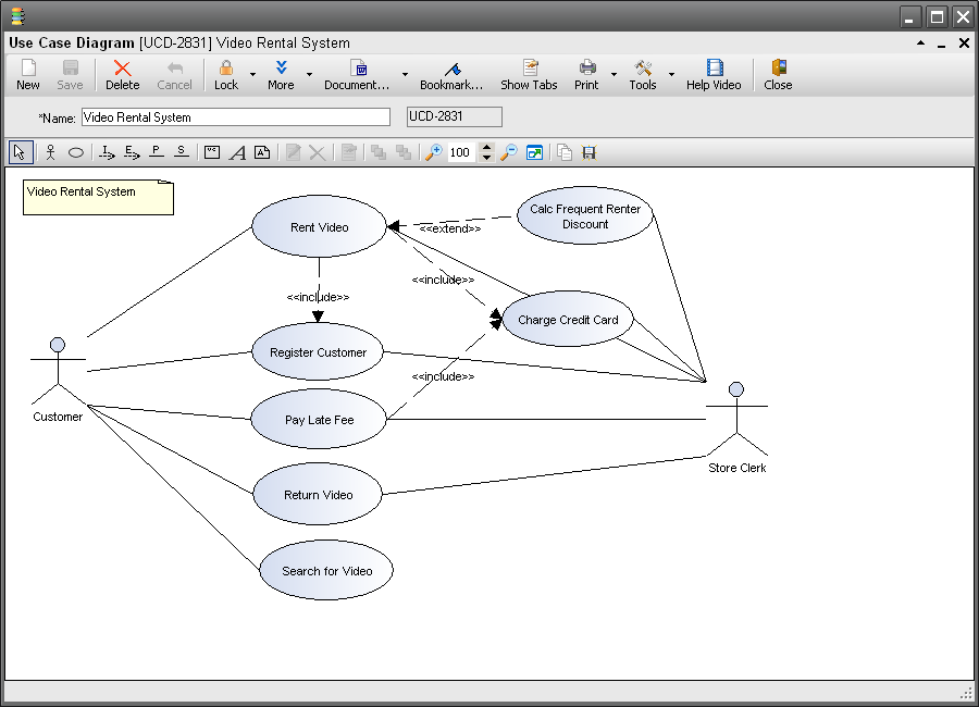
Just as with component diagrams, these groupings are represented as file folders.From the search results, select UML Use Case. Packages: A UML shape that allows you to put different elements into groups. For example, Psycho Killer is outside the scope of occupations in the chainsaw example found below. All use cases outside the box would be considered outside the scope of that system. System boundary boxes: A box that sets a system scope to use cases. In complex diagrams, it is important to know which actors are associated with which use cases.

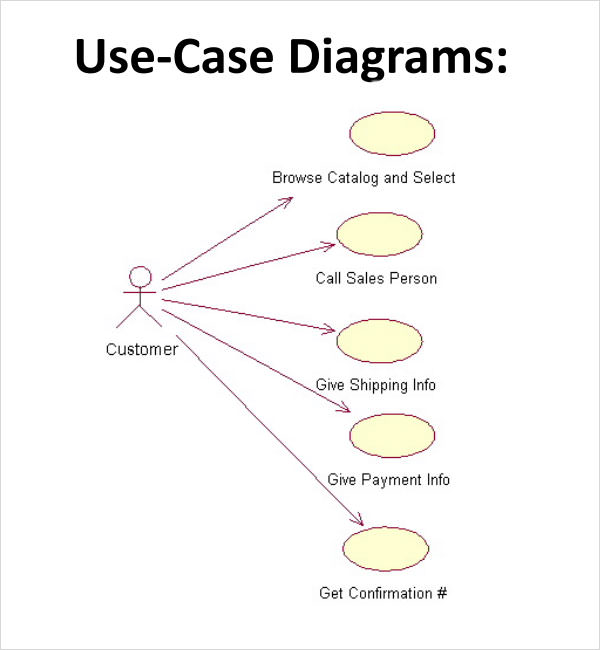
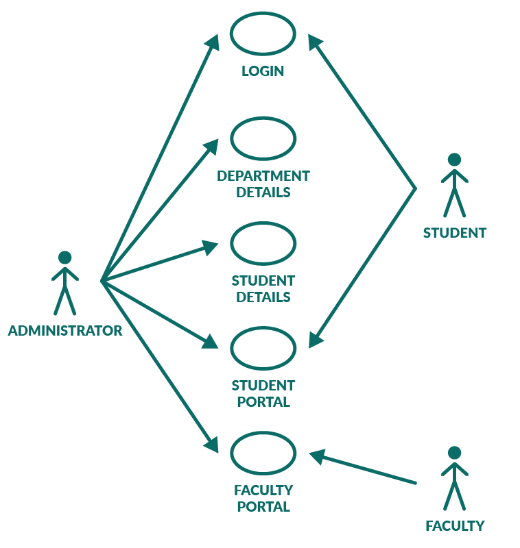
Use cases: Horizontally shaped ovals that represent the different uses that a user might have.Īctors: Stick figures that represent the people actually employing the use cases.Īssociations: A line between actors and use cases.

Here are all the shapes you will be able to find in Lucidchart: You can use this guide to learn how to draw a use case diagram if you need a refresher. The notation for a use case diagram is pretty straightforward and doesn't involve as many types of symbols as other UML diagrams.


 0 kommentar(er)
